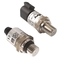
Druckschalter PS97
-

PS97 Serie (Fitting angle) -

PS97 Serie (Connector angle) -

PS97 - G1/4, M12 connector type (Fitting angle) -

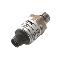
PS97 - G1/4, M12 connector type (Connector angle) -

PS97 - R1/4, DT connector type (Fitting angle) -

PS97 - R1/4, DT connector type (Connector angle)
-

PS97 Serie (Fitting angle) -

PS97 Serie (Connector angle) -

PS97 - G1/4, M12 connector type (Fitting angle) -

PS97 - G1/4, M12 connector type (Connector angle) -

PS97 - R1/4, DT connector type (Fitting angle) -

PS97 - R1/4, DT connector type (Connector angle)
- ●Um einen Kauf zu tätigen, wenden Sie sich an die Verteiler unten.
Verkaufskanal Überprüfen Sie die Verteiler.- VERKAUFSKANALKlicken Sie hier, um den Verteiler zu überprüfen.
Neu eingeführter Druckschalter für mittleren bis hohen Druckbereich
Der neue Dünnen Schichten Druckschalter der Serie PS97 verfügt über einen großen Temperaturbereich (-40~125 °C) und eine hohe Genauigkeit von ±1 % F.S. (bei 0~80 °C) mit wasserdichter IP67-Schutzstruktur. Darüber hinaus große Auswahl an Druckbereichen von 0 bis 1,0 MPa, 2,5 MPa, 5,0 MPa, 10 MPa, 25 MPa, 40 MPa, 50 MPa, 80 MPa, geeignet für einen breiten Druckbereich von mittlerem bis hohem Druck. Die Hauptzielmärkte sind Werkzeugmaschinen, Spezialfahrzeuge, Spritzgussmaschinen, Hochdruckwaschmaschinen und Hydraulikanlagen. Wir bestätigen und stellen den Betriebsmodus, den Druckeinstellpunkt zum Schalten und die gewünschte Hysterese vor dem Versand ein.
-
Breiter Betriebstemperaturbereich: -40~125 °C
-
Hohe Präzision und hohe Zuverlässigkeit durch SUS630 äquivalente Membran, kein Silikonöl *Hohe Genauigkeit von ±1 % F.S. at 0~80 °C
-
Wasserdicht (IP67) mit geschweißter und integrierter Steckverbinderstruktur
-
Vielfältige Auswahlmöglichkeiten des Druckbereichs für mittleren-hohen Druckbereich (1~80 MPa)
-
Betriebsart und Druckeinstellpunkt zum Betätigen des Schalters werden im Voraus nach Ihren Wünschen eingestellt / Hysterese ebenfalls willkürlich einstellbar
-
UL anerkannt, CE-Marking anwendbar
-
Bitte teilen Sie uns den gewünschten Druckeinstellbereich usw. mit
Bitte teilen Sie uns beim Kauf Ihre Bestätigungsentscheidungen unten mit, vorausgesetzt, vorausgesetzt, Sie wählen den Nenndruckbereich im Voraus.
- Wählen Sie die Schaltausgangspunkte [Erforderlich]: 1 oder 2
- Wählen Sie die Betriebsart [Erforderlich]: Wählen Sie aus den folgenden beiden;
Normalerweise geöffnet:Schalten Sie dort ein, wo der Druck Ihre Einstellung erreicht hat.Normalerweise geschlossen:Schalten Sie das Gerät aus, wenn der Druck Ihre Einstellung erreicht hat.
*Wenn Sie den Schalterausgang von zwei Punkten auswählen, müssen Sie ihn an jedem Schalter einstellen. Die folgenden Elemente sind ebenfalls identisch.
- Der gewünschte Drucksollwert zum Betätigen des Schalters [Erforderlich]:
( MPa) ※Kann auf den ersten Dezimalpunkt gesetzt werden
Der Sollwert muss innerhalb von 3 bis 97 % F.S. des Betriebsdruck.
- Möchten Sie von Ihrem Willkürlichen auch über Hysterese einstellen? [Optional]:
Ja ( % F.S.) oder Nein
Die Hysterese, dh der Rücksetzpunkt nach dem Schaltvorgang, kann auf die gewünschte Rate eingestellt werden. Es muss auf 2% F.S. oder höher am Schaltbetriebssollwert (über der Einstellung). Wenn Sie den Rücksetzpunkt nicht nach Ihrem Ermessen festlegen möchten, richten wir ihn auf 2% F.S. des Schaltbetriebssollwerts.
- *Die obige Bestätigung finden Sie in [Abb.1] unten.
[Abb.1 Druckeinstellbereich und Hysteresemodus]

Standardspezifikationen
| Item | Model number (PS97-✽✽✽P) | ||||||
|---|---|---|---|---|---|---|---|
| Pressure range | 103P | 253P | 503P | 104P | 254P | 404P | 804P |
| Pressure reference | Gauge | ||||||
| Rated pressure (MPa) | 1.0 | 2.5 | 5.0 | 10.0 | 25.0 | 40.0 | 80.0 |
| Maximum pressure (MPa) | 4.0 | 4.0 | 10.0 | 20.0 | 50.0 | 80.0 | 100.0 |
| Break-down pressure (MPa) | 7.0 | 7.0 | 50.0 | 100.0 | 250.0 | 400.0 | 400.0 |
| Operating temp. range | -40 ~ 125 °C 5 | ||||||
| Storage temp | -40 ~ 125 °C 5 | ||||||
| Operating humidity | 95 % RH maximum (No condensation) | ||||||
| Pressure medium | Gases and liquids compatible with SUS630 | ||||||
| Insulation resistance | 100 MΩ minimum (500 VDC) | ||||||
| Pressure port | G 1/4, G 3/8, R 1/4 | ||||||
| Net weight/Outline | Approx. 50 g (No cable) | ||||||
| Drip-proof structure | IP67 | ||||||
| Cable |
Sold separately |
||||||
| Operating voltage |
9 ~ 36 V |
||||||
| Consumption current | 10 mA maximum | ||||||
Schalter Ausgang
| Number of output | 2 (Connecter: M12 type) or 1 (Connector: DT04-3P type) |
|---|---|
| Output interface | NPN open collector [*If you would like to purchase PNP open collector type, please contact us separately.] |
| Setting method | Set by software |
| Adjustable range | 3 ~ 97 % F.S. |
| Operating mode | Hysteresis (Refer to above Fig.1) |
| Overall accuracy | ±1.0 % F.S. (0 ~ 80 °C) ±1.5 % F.S. (25 ~ 100 °C) ±2.5 % F.S. (-40 ~ 125 °C) |
| Hysteresis | Adjustable by software (Should be more than 2 % F.S.) |
| Switching capacity | 0.25 A/ch. Maximum (Connecter: M12 type), 0.5 A Maximum (Connecter: DT04-3P type) |
| Residual voltage | 0.65 V Maximum |
| Output load | Vopr / (0.5 A x 0.5) ≦ RL ≦ 10kΩ |
| Response | 10 ms Maximum |
Umwelteigenschaften
| Test item | Test conditions (at 25 ±5 °C) | Permissible change |
|---|---|---|
| Vibration | 10 ~ 500 Hz, 98.1 m/s2, 3 directions for 2 hours each | Change in analog output accuracy after the testas are ±1 % F.S. maximum. |
| Shock | 490 m/s2 3 directions for 3 times each | |
| Pressure cycling | 0 ~ Rated pressure / Rated pressure range 106 cycles | |
| Moisture resistance | 40 °C, 90 ~ 95 % RH, 240 hrs. |
Modellnummer Bezeichnung
| PS97 | - | 103 | P | - | M | G2 | - | J |
|---|---|---|---|---|---|---|---|---|
|
Series name |
Rated pressure range 103:1.0 MPa 253:2.5 MPa 503:5.0 MPa 104: 10 MPa 254: 25 MPa 404: 40 MPa 804: 80 MPa |
Pressure reference P:Gauge (Positive) |
Connector M:M12×1 D:DT04-3P |
Fitting G2:G1/4 R2:R1/4 (Not include 80 MPa) |
Seal type J:With JIS O-ring Blank:No O-ring |
List of Part Numbers
| Rated pressure range | Fitting / Connector | |||
|---|---|---|---|---|
| G2 (with O-ring Seal) | R2 | |||
| M: M12 | D: DT04-3P | M: M12 | D: DT04-3P | |
| 0 ~ 1.0 MPa | PS97-103P-MG2-J | PS97-103P-DG2-J | PS97-103P-MR2 | PS97-103P-DR2 |
| 0 ~ 2.5 MPa | PS97-253P-MG2-J | PS97-253P-DG2-J | PS97-253P-MR2 | PS97-253P-DR2 |
| 0 ~ 5.0 MPa | PS97-503P-MG2-J | PS97-503P-DG2-J | PS97-503P-MR2 | PS97-503P-DR2 |
| 0 ~ 10 MPa | PS97-104P-MG2-J | PS97-104P-DG2-J | PS97-104P-MR2 | PS97-104P-DR2 |
| 0 ~ 25 MPa | PS97-254P-MG2-J | PS97-254P-DG2-J | PS97-254P-MR2 | PS97-254P-DR2 |
| 0 ~ 40 MPa | PS97-404P-MG2-J | PS97-404P-DG2-J | PS97-404P-MR2 | PS97-404P-DR2 |
| 0 ~ 80 MPa | PS97-804P-MG2-J | PS97-804P-DG2-J | ----- | ----- |
Umrissmaße
● Anschluss: Anschluss: Typ DT04-3P (Schaltausgang: 1)

| Model | A’ | B’ | Fitting | CAD |
|---|---|---|---|---|
| PS97-✽✽✽P-DG2-J | 64.2 | 40.75 | G 1/4 | |
| PS97-✽✽✽P-DR2 | 66.5 | 43.05 | R 1/4 |
● Anschluss: Anschluss: Typ M12 (Schaltausgang: 2)

| Model | A’ | B’ | Fitting | CAD |
|---|---|---|---|---|
| PS97-✽✽✽P-MG2-J | 52.25 | 40.75 | G 1/4 | |
| PS97-✽✽✽P-MR2 | 54.55 | 43.05 | R 1/4 |
Passend zu
-
● G 1/4
Products for 5.0 MPa or more of the standard line-up are equipped with a snubber. -
● R 1/4
Products for 5.0 MPa or more of the standard line-up are equipped with a snubber.
Pinbelegung
-
● Anschluss: Typ DT04-3P
Pin A Vcc (Power) Pin B GND (Common) Pin C SW (Output) -
● Anschluss: Typ M12
Pin 1 Vcc (Power) Pin 2 SW2 (Output) Pin 3 GND (Common) Pin 4 SW1 (Output) Pin 5 N.C.
Verkabelung (schematisch)

Output Load: RLmin.=Vopr/(0.5Ax0.5) , RLmax.=10kohm
Optionales Kabel (separat erhältlich)
● P/N: PS97-D152C (for DT04-3P connector)
| No. | Color | Function |
|---|---|---|
| A | Brown | Power |
| B | Blue | GND |
| C | White | SW1 |
● P/N: PS97-M152C (for M12 connector)
| No. | Color | Function |
|---|---|---|
| 1 | Brown | Power |
| 2 | White | SW2 |
| 3 | Blue | GND |
| 4 | Black | SW1 |
| 5 | Gray | N.C. |
Vorsichtsmaßnahmen beim Betrieb
(DT cable’s thermal withstand is 105 °C, M12 is 90 °C)
Vorsichtsmaßnahmen bei der Wartung
Gewährleistung
However, the following shall be excluded from the warranty:
Failure or damage caused by improper use and careless operation in violation of the Operating Instructions.
The term “Warranty” herein referred to shall imply the warranty for the product unit only, and damages from failure of the product shall be excluded.
This product is not intended to be used for equipment that may cause direct harm to life or body, or equipment that may cause significant physical damage. (Aerospace and space related equipment, railway vehicles, nuclear power equipment, military equipment, etc.)
We are not liable for any damages arising from the use of this product for purposes not intended by us.
Unterlagen
- ●Die oben genannten Inhalte können ohne vorherige Ankündigung geändert werden.


