Toggle switch 8A
- ●Um einen Kauf zu tätigen, wenden Sie sich an die Verteiler
oder nutzen Sie den stehenden Online-Shops unten.
Verkaufskanal Überprüfen Sie die Verteiler.- VERKAUFSKANALKlicken Sie hier, um den Verteiler zu überprüfen.


Standard Bat Toggle Switch
-
The 8A series has a 10.5mm bat toggle.
-
Terminal style : Solder, PC Straight
-
Contacts : Silver or gold.
-
Epoxy resin case : UL94V-0 self-extinguishing epoxy.
-
Actuator styles : Over 30 actuator variations.
-
Insulation between terminal and ground : 4 mm minimum.
-
Prevention of flux entry The epoxy resin seal on bottom of the switch helps prevent the entry of solder and flux.
-
Insulation barrier : Insulation barrier design between poles helps prevent short-circuiting between poles ensuring high reliability.
-
UL Recognized product File No.E43275 CSA Certified product File No.LR38341
Part Number Designation
| 8 | A | 1 | 01 | 1 | C | - Z |
|---|---|---|---|---|---|---|
|
Series |
Actuator shape A: Standard toggle |
No. of poles 1: 1 pole 2: 2 poles 3: 3 poles 4: 4 poles |
Switching function 01: ON-ON 02: ON-OFF-ON 06: ON-(ON) 10: ON-ON-ON |
Terminal style 1: Solder 2: PC straight |
Contact material / Plating Blank: Bs+Ag or Cu+Ag / Silver plated (Ag) / Silver plated (Ag) C: Bs+Ag or Cu+Ag / Gold plated (Ni+Au) / Gold plated (Ni+Au) Bs=Brass, Ag=Silver, Cu=Copper, |
◆Terminals

List of Part Numbers
| Part No. | Terminals | No. of poles | SW function | CAD |
|---|---|---|---|---|
| Part No.:8A1011-Z | Solder | 1 pole | ON-ON | |
| Part No.:8A1011C-Z☆ | Solder (Gold) | 1 pole | ON-ON | |
| Part No.:8A2011-Z | Solder | 2 poles | ON-ON | |
| Part No.:8A2011C-Z☆ | Solder (Gold) | 2 poles | ON-ON | |
| Part No.:8A3011-Z☆ | Solder | 3 poles | ON-ON | |
| Part No.:8A4011-Z☆ | Solder | 4 poles | ON-ON | |
| Part No.:8A1021-Z | Solder | 1 pole | ON-OFF-ON | |
| Part No.:8A2021-Z☆ | Solder | 2 poles | ON-OFF-ON | |
| Part No.:8A4101-Z★ | Solder | 4 poles | ON-ON-ON | |
| Part No.:8A1012-Z | PC straight | 1 pole | ON-ON | |
| Part No.:8A1012C-Z☆ | PC straight (Gold) | 1 pole | ON-ON | |
| Part No.:8A2012-Z | PC straight | 2 poles | ON-ON | |
| Part No.:8A3012-Z | PC straight | 3 poles | ON-ON | |
| Part No.:8A1022-Z☆ | PC straight | 1 pole | ON-OFF-ON | |
| Part No.:8A1022C-Z☆ | PC straight (Gold) | 1 pole | ON-OFF-ON | |
| Part No.:8A2022-Z☆ | PC straight | 2 poles | ON-OFF-ON |
★: Made to order products
Optional Accessories
| Actuator | Part No. | Color | Outline Dimensions |
|---|---|---|---|
| Color Cap | 140000470030 | White |  |
| 140000470098 | Red | ||
| 140000470031 | Black | ||
| 140000470037 | Gray | ||
| 140000470038 | White |  |
|
| 140000470100 | Red | ||
| 140000470077 | Gray | ||
| Boot | 140000470422 |  |
|
Common Specifications
| Rating Max. | Silver Contact:AC125V 6A AC250V 3A DC30V 4A Gold Contact:AC125V 6A AC250V 3A DC20V 25mA |
|---|---|
| Initial contact resistance | Silver Contact:10mΩ Max. (DC2~4V 1A) Gold Contact:20mΩ Max. (AC200μV 1.5mA) |
| Initial dielectric strength | AC1500V 1minute |
| Initial insulation resistance | 1000MΩMin. ( DC500V) |
| Electrical life | Alternate type:50,000cycles Momentary type:25,000cycles |
| Operating temperature range | -30~+85℃ |
| Storage temperature range | -40~+85℃ |
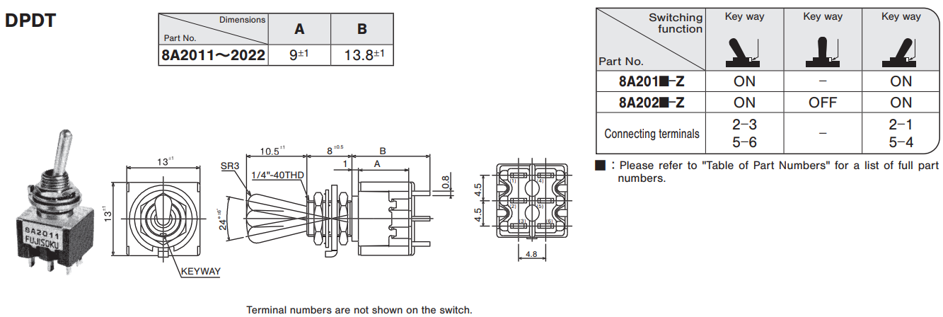
Outline Dimensions
(Unit:mm)


Precautions
Soldering Specifications
- Manual soldering/Device :Solder iron ①420℃ Max. 3 sec. Max.
- Auto soldering/275℃ Max. 6 sec. Max.
- The above-stated soldering conditions shall apply only to switches with straight terminals. Auto soldering is not possible with right-angle terminals. Switches with right-angle terminals should be soldered manually according to the conditions specifi ed in (1) above.
- When soldering two or more terminals to the common land, use the solder resist to isolate the terminals.。
Flux Cleaning
- Solvent : Fluorine or Alcohol type.
- 8A/B/C/D/E/F/J series are not washable. To wash the PC board, clean the soldering surface of the PC board with a brush so that the switch is not exposed to the cleaning solution.
- Cleaning after soldering should be done after the terminal temperature falls to 90℃ or below, or after leaving the switch for fi ve minutes or longer at room temperature.
Mounting
- Do not bend the terminals before mounting the switch on the PC board.
- After mounting the switch, do not place the device in such a way that the device weight will be applied on to the actuator of the switch.
- For switches with straight terminals, solder the switch on the PC board after fi xing the switch on the panel with a nut.
Panel Cut-Out Dimensions
- With Locking Ring:Panel thickness 2.5 mm Max.
- Without Locking Ring:Panel thickness 3.5 mm Max.

PC Hole Layouts

Standard Accessories

● Numbers in the above chart show the quantities of each accessories enclosed with the switch.
Three ON Switches
These switches are designed so that the Switching Function will be ON in all three positions. Extra wiring is required by the customer to get the three ON options. Please see below.
8A4101-Z 2 Circuit 3 Contacts

※External wiring (to be wired by the customer)
8 Series Toggles Selection Table

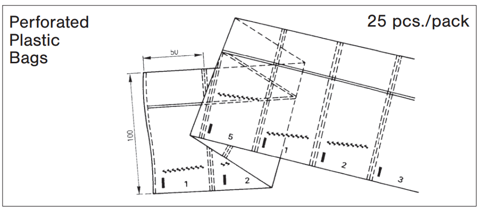
Packaging Specification
(Unit:mm)

Unterlagen
RoHS-Zertifikat
- ●Die oben genannten Inhalte können ohne vorherige Ankündigung geändert werden.


