NIDEC COMPONENTS logo

LIST

×

×


Products

Distributor

Global-En

×

For LiDAR scanning solution Polygon Mirrors and Scanner Motors Vol.3

For LiDAR scanning solution Polygon Mirrors and Motors Vol.3

  • Chapter 10  New!
  • Recommend Mirror Thickness ReductionThinning(2)
    (2) Technological Approach
Laser scanning unit
Laser scanning unit

Here is an animation on the right illustrating laser scanning with a polygon mirror within the laser printer head.
The thickness of the polygon mirrors significantly affects the productivity of applications utilizing laser scanning. Reducing of the mirror thickness is highly effective for reducing production costs, as proven in industrial equipment that has achieved remarkable advancements in mirror thinning through years of technological innovation, optical system improvements have played a significant role specifically. For your reference, we'll guide you through the process of gradual mirror thinning along with the evolution of optical technologies in laser printers.

Please note that the figures included in the explanations below all depict the structure of the laser printer head as viewed from an overhead angle. They are considerably distorted from reality to make it easier to understand the technical points. Kindly keep this in mind.


1. Post-objective optical system

By placing a “collimator lens” as imaging lens upstream of the rotating mirror, the diverging laser can be transformed into a smaller straighten laser. However, if laser imaging onto a flat surface typified by laser printers is necessary, the laser scanned by the rotating mirror reaches the focal point on an arc, so the focal points of the laser won't align between the central and edge parts of the photosensitive drum unless a larger focal length is used. Consequently, a thick mirror is required at this stage yet. (See figure below)

2. Pre-objective optical system

Instead of increasing the laser diameter an imaging lens such as a “fθ Lens” can be inserted which functions to keep the scan speed constant. Although the lens diameter is large, the image surface can now be flattened resulting in a shorter focal length and a thinner mirror. (See figure below)

3. Compensating for dynamic error

By placing an optical system such as a “cylindrical lens” that focuses light in only one axis upstream of the mirror for correcting variations in the perpendicularity of the mirror surface. As secondary effect, this creates a horizontal line image which can be used to significantly reduce the mirror thickness. This is considered a major branching point that contributes to the thinning of the mirror, from a technological standpoint. (See image below)
 

4. Wide angle scanning using an aspherical lens

The previously mentioned fθ lens had the drawback of limiting the scanning angle. However, the use of an “aspherical lens” enabled a wide scanning angle with a short focal length allowing further reduction in the overall height of the mirror. It also contributed to the downsizing of the printer itself. (See figure below)
 

Advocating Polygon Mirror thickness reduction for LiDAR

Achieving reducing the thickness of polygon mirrors in LiDAR applications would lead to improved productivity and cost reduction, thus increasing expectations for even wider adoption in the future. Reducing the thickness of mirrors also demands precision in laser diodes and the application of optical system technology in LiDAR development.

As our company boasts a world-leading supply record for thin polygon mirrors used in industrial applications, similar achievements can be applied to LiDAR. Taking the example of the technological evolution in industrial mentioned above as reference, we strongly encourage considering the polygon mirror thickness reduction for LiDAR applications as well.
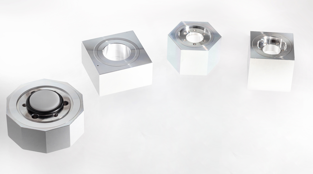
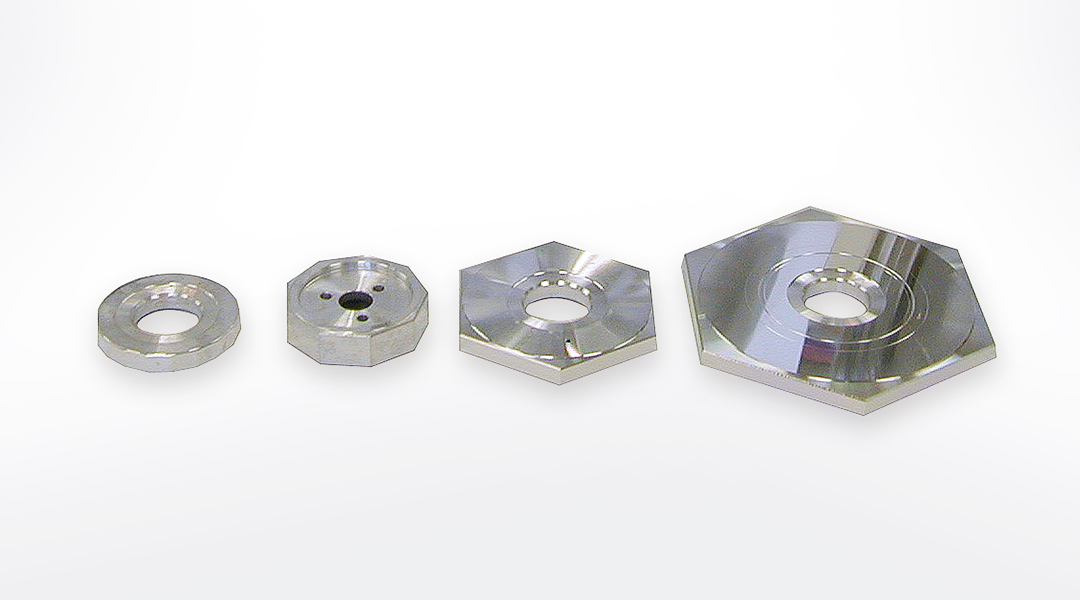
Polygon mirrors for LiDAR
  Polygon mirrors for LiDAR


Polygon mirrors for Industrial 
Polygon mirrors for Industrial 
 

ー Fin ー

page top