Lever&rocker switch ALE
Standard Lever & Rocker Switches
-
High reliability The twin-contact clip mechanism is employed for the contact section to ensure high reliability.
-
Process sealed structure All types of the switch feature the completely sealed structure.
-
Designed for dry circuit applications Since the contacts are gold-plated, the switches are best suited for use in the dry circuit areas.
-
Designed for PC board applications The terminal pitches are all in inch size (2.54 mm).
-
Improved operability The independent detent structure provides a light operating touch.
-
All models are of UL approved type. (File No. E42375)
Part Number Designation
| A | LE | 1 | D - | 2 | M | 4 | - 10 - Z |
|---|---|---|---|---|---|---|---|
|
Series |
Actuator type LE: Lever / Rocker |
No. of poles 1: 1 pole 2: 2 poles |
SW function D: On-On E: On-Off-On F: On-(On) G: (On)-Off-(On) Terminal rows pitch: 0.1" |
Terminals 2: PC straight 5: R/A 0.2" pitch |
Actuator shape M: Standard |
Bracket 4: With |
Clip mechanism |

List of Part Numbers
| Part No. | SW function | Circuit | Terminals | CAD |
|---|---|---|---|---|
| Part No.:ALE1D-2M4-10-Z | ON-ON | SPDT | PC straight | |
| Part No.:ALE1E-2M4-10-Z☆ | ON-OFF-ON | SPDT | PC straight | |
| Part No.:ALE1F-2M4-10-Z☆ | ON-(ON) | SPDT | PC straight | |
| Part No.:ALE1G-2M4-10-Z☆ | (ON)-OFF-(ON) | SPDT | PC straight | |
| Part No.:ALE2D-2M4-10-Z☆ | ON-ON | DPDT | PC straight | |
| Part No.:ALE1D-5M4-10-Z☆ | ON-ON | SPDT | R/A 0.2" pitch | |
| Part No.:ALE2D-5M4-10-Z☆ | ON-ON | DPDT | R/A 0.2" pitch |
★: Made to order products
Standard Accessories
| Actuator | Part No. | 色調 | Outline dimensions |
|---|---|---|---|
| Lever | 140000050624 | White |  |
| 140000050626 | Red | ||
| 140000050625 | Black | ||
| 140000050630 | Gray | ||
| Rocker | 140000480673 | White |  |
| 140000480675 | Red | ||
| 140000480674 | Black |
Specifications
| Rating | Max:AC/DC60V 50mA Min:AC/DC20mV 1μA UL: AC/DC48V 50mA |
|---|---|
| Initial contact resistance | 50mΩ max. ( 1.5mA 200μVAC) |
| Dielectric strength | 250VAC 1 minute |
| Insulation resistance | 500MΩ min. ( 500VDC) |
| Electrical life | 10,000 cycles at maximum rating 50,000 cycles at 0.4VA min(D,E type) 30,000 cycles at 0.4VA min(F,G type) |
| Operating temperature range | -20~+85℃ |
| Storage temperature range | -40~+85℃ |
Outline Dimensions
(Unit:mm)


PC Hole Layouts

Soldering Specifications
- Manual Soldering
Device : Soldering iron
380℃, Max.; 3 seconds, Max. - Auto Soldering Device : Jet wave type or dip type
275℃, Max.; 6 seconds, Max.

◆Pre-heating should be done at temperatures ranging from 80℃ to 120℃ and within 120 seconds.
Note: Mount the accessories of knob and lever after the soldering.
Flux Cleaning
- For the solvent, use the fl uorine- or alcohol-based solvent.
Solvent: Fluorine or Alcohol type - Cleaning after soldering should be done after the terminal temperature falls to 90℃ or below, or after leaving the switch for fi ve minutes or longer at room temperature.
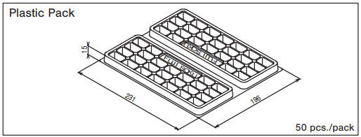
Packaging Specification
(Unit:mm)

Documents
Environmental Certificate
- ●The above contents and descriptions are subject to change without notice.


