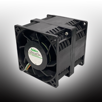
DC Brushless Axial fan C80H12BS4ME-07
High Airflow, Low Power Consumption And Long Lifespan
- 80 x 80 mm 12 VDC Brushless Fan
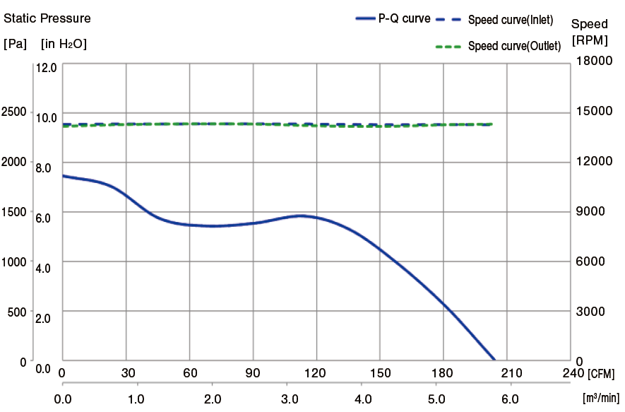
- High Airflow (203.00 CFM @ 5.75 m3 /min )
- Low Current Consumption 14.30 A (Nominal) 15.73 A (Peak)
- Long Lifespan 70,000 hours @ 40°C & 65 % R.H.(L10 Expectancy)
- Ball Bearings
- Counter Rotor Fan
- PWM Speed Control With Tach Output
- The highly reliable fan motor is widely used in various applications
- Manufactured by NIDEC CORPORATION
Characteristic Curve
1.Mechanical Specifications
| Housing material | PBT (UL94 V-0) |
|---|---|
| Impeller material | PBT (UL94 V-0) |
| Bearing | Ball bearings |
| Mass | About 465 g |
| Life expectancy L10 | 70,000 hours 1)At 40°C (65 % R.H.), continuous operation at rated voltage. 2)Life is defined when the motor speed decreases more than 30% against its initial speed. |
2.Electrical Specifications
| No. | Item | Specifications | Remarks |
|---|---|---|---|
| 2-1 | Rated voltage | 12 VDC | |
| 2-2 | Operating range | 10.8~13.2 V | (Note 5) |
| 2-3 | Current consumption | Max.15.73 A 14. 30 A (Nominal) |
In free air at rated voltage (Note 4) (Note 6) |
| 2-4 | Power consumption | Max.188.76 W 171.6 W (Nominal) |
In free air at rated voltage |
| 2-5 | Rated speed | Min. 12960 min-1 14400 min-1 (Nominal) Max. 15840 min-1 |
In free air at rated voltage Intake side (Note 4) |
| 2-6 | Maximum air flow | Min. 4.91 m3 /min (173.3 CFM) 5.75 m3 /min (203.0 CFM) |
At rated voltage At zero static pressure (Note 4) |
| 2-7 | Maximum static pressure | Min.1504 Pa (6.04 inch-H2O) 1955 Pa (7.85 inch-H2O) |
At rated voltage At zero air flow (Note 4) |
| 2-8 | Acoustic noise | Max. 83.5 dB (A) 80.5 dB(A)(Nominal) |
In free air at rated voltage
|
| 2-9 | Operating temperature | -10°C~70°C (Normal humidity) | |
| 2-10 | Storage temperature | -40°C~75°C(Normal humidity) | |
| 2-11 | Direction of rotation | Inlet :CCW Outlet:CCW From air intake of fan |
|
| 2-12 | Direction of air flow | label side discharge | |
| 2-13 | Insulation resistance | Min.10 MΩ | At 500 VDC between frame and leads |
| 2-14 | Dielectric strength | Must withstand 500 VAC 1min | Max. 1mA between frame and leads (Usually inspect at 600 VAC,1 sec,1 mA) |
| 2-15 | Protection | Current limit protection | (Note 3) |
| Hot swap |
- Note1: The above standard should be the specified value at normal temperature (23°C) and normal humidity (60~65%) unless otherwise notice.
- Note2: In the case that power is turned on during fan rotor is locked, the fan shall attempt to restart at a typical repetition rate(Temperature rise will be prevented). The fan will automatically restart when the locked rotor condition is released.
- Note3: Power supply voltage must not be applied between signal output line and any other line directly. Reverse polarity protection is effective to just switch the positive and negative power line.
- Note4: Control signal(Blue & green lead wires) should be applied 2.6 to 6.0 V or should be open.
- Note5: 40 V~60 V operating voltage range is for continuous DC voltage. Power supply voltage ripple 5% maximum.
- Note6: The max value of current consumption does not represent the peak value.
3.Provision of Revolution Signal
3-1 Output of Revolution Signal
● Output type: open collector type
● Electrical specification
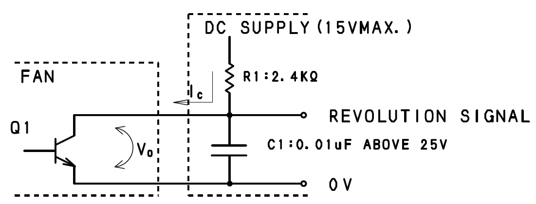
Remark: As for measuring VOL, it is necessary to put cr low pass filter which is constructed of R1 and C1. The time constant of R1 x C1 is to be more than 24us such as R1=2.4 kΩ C1=0.01 uF.
● Absolute maximum specification
Collector current IC=10 mA Max.
Release Voltage VOH= 15 V Max.
● Electrical characteristics
Saturation Voltage VOL = 0.8 V Max.
At IC=5 mA
● Output waveform
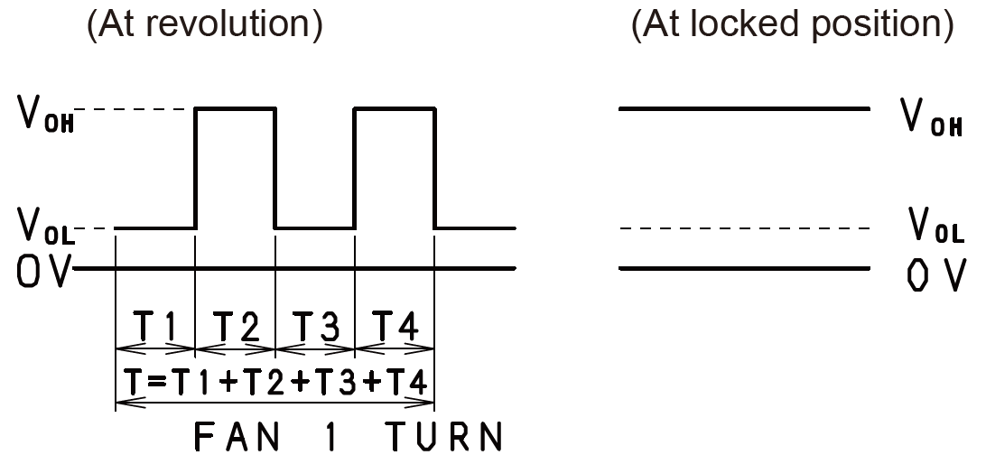
- Remark: At locked position, output becomes VOH OR VOL .
- T=T1+T2+T3+T4=60/N (Sec) N: Fan Speed (min-1)
- DUTY =T1/T1+T2= 50±10%
⚠ CAUTION
Please be careful that revolution signal lead wire (Yellow & white wire) shall not have any voltage directly applied. (It should damage inner circuit.)
4.PWN Control
4-1 TYPE
● The method of active/inactive drive mosfet for speed control.
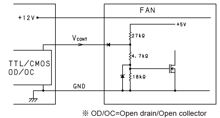 *Actual machine side is TTL/CMOS PWM controlled.
- VCONT is above 2.6 V ··· Fan should run maximum speed.
- VCONT is below 0.5 V ··· Fan should run minimum speed.
- Control wire should accept PWM control, PWM frequency is from 20 kHz to 32 kHz.
4-2 PWM CONTROL SIGNAL
● Signal voltage range: 0~6.0 VDC

- The frequency for control signal of the fan shall be able to accept at 20 kHz-32 kHz. PWM signal with 3.3 VDC TTL/COMS level.
- The preferred operating point for the fan is 25 kHz, and duty cycle from 0% to 100%. If the PWM control wire connect to ground, the rotor will spin at minimum speed.
- At 100% duty cycle, the rotor will spin at maximum speed. If the PWM control wire open, the rotor will spin at maximum speed.
4-3 SPEED VS PWM CONTROL SIGNAL, AT RATED VOLTAGE
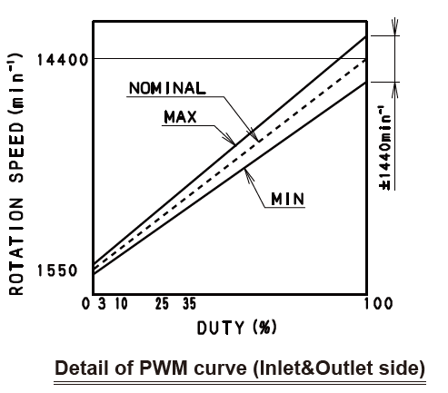
| Duty cycle (Positive)(%) | Speed min-1 |
|---|---|
| Inlet&Outlet side | |
| 0 | 1550±300 |
| 100 | 14400±1440 |
- Note: The standards should be the specified value at normal temperature (23°C) and normal humidity (60~65%), free air and 54 V 25 kHz unless otherwise notice.
5.Special Test
5-1 VIBRATION TEST
- Standards for items 2-3~2-8 and 6-2 should be met after 30 minutes 0.2 mm amplitude, 55 Hz vibration in each direction: up-down, right-left, forward-back, in nonoperating condition.
5-2 SHOCK TEST
- Standards for items 2-3~2-8 and 6-2 should be met if the fans fall naturally from a height of 30cm in the packing box for each direction.
*Dimensions of Packing Box (W x D x H) : 360 x 540 x 220 (mm)
6.Others
6-1 CONNECTION
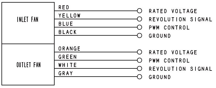
6-2 LOCKED ROTOR
No damage shall be found for continuous 1 hour at locked rotor.
6-3 ⚠ CAUTIONS IN INSTALLATION OF FAN MOTORS
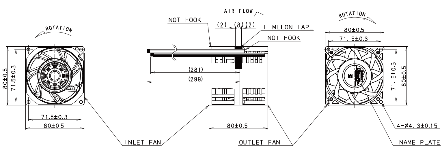
- Please consider system layout not to place any obstacles within 3mm from the fan housing edge of inlet side (Impeller side).
- In case of screwing the fan housing, flatness of installation surface should be max. 0.1, otherwise the housing may transform and interfere with the impeller.
- The fan should not get any impact or vibration during rotation. When vibration or impact is applied to the fan during rotation, the fan may break by interfering with obstacle in the system.
- Please fix the fan in the system so that it will not rattle. Vibration of the fan may cause contact between the fan and the system, which will generate noise.
- Please do not place any obstacle near outlet and inlet side of the fan.
- Placing obstacles near the fan may deteriorate air flow.
- It may cause cooling performance reduction as well as fan motor life deterioration due to heavy load on the bearings.
- This model is designed to be installed as the screw in flange one side(Refer to figure((a)). In case of installations as the screw through both flanges (Refer to figure ((b)).
- It may cause damages on the housing and/or interference between the impeller and the housing because of the housing deform.
- For any usage that does not meet above conditions, please evaluate at user's side or consult with us. R40W12BGNL9-07 DC BRUSHLESS AXIAL FAN Detail of PWM curve(Outlet side)

6-4 ⚠ USAGE OF FAN MOTOR
- Please do not put resistors or other electronic components on the extension of the fan motor lead wires for the purpose of fan motor speed reduction.
- It may make the voltage to the fan fluctuate and become lower than lower limit of operating voltage range.
- In this case, there may be such failures like no start or unstable rotation of fan motor.
6-5 ⚠ EARTH · ELECTROSTATIC PROTECTION
- Electrification and leakage can cause motor circuit or semiconductor failure.
- Proper grounding is required for soldering iron and conveyer belt during motor terminal or lead wire soldering to mechanism or set. (±200 V or less)
7.Special Items
7-1 WARRANTY
- Our warranty is limited to the replacement of failed fan at free of charge, if and only if the failure is found within two years after it was shipped out from our production facility and if the cause of the failure is proven to be attributable to the supplier.
- Our liability does not extend to the consequential damages caused by the failed fan.
7-2 NOTE
Please consider having an independent protection system in the customer's instruments in the event that the fan should stop operating.
7-3 POWER SOURCE
Brushless DC fans are designed to be used at DC power source with bypass capacitor. We would recommend you to use DC power source which is filtered ripple and noise.
- Fans are designed to perform as expected when stable voltage is supplied.
- Fluctuation of the voltage between Vcc(+) and GND while the fan is powered must be within the specified operating voltage range.
- Fluctuation cycle of the voltage between Vcc(+) and GND while the fan is powered must be longer than the fan's rotation cycle.
- GND of the fan must be kept below the voltage of its Vcc(+) when the voltage is switched ON/OFF or the fan is not running.
- Devices that use the fans are supposed to be designed so that the voltage applied on the revolution signal is not affected by power ON/OFF.
7-4 ENVIRONMENT-RELATED SUBSTANCES
Based on RoHS3, cadmium, lead, mercury and compound of these substances and hexavalent chromium compound, Polybromo bi-phenyl(PBB) and polybromo di-phenyl ether(PBDE) are not included in this product
8.Outline Dimensions
(Unit: mm)
| Color | Function | Lead wire |
|---|---|---|
| Red | Inlet +12V | UL3265, AWG 18 |
| Black | Inlet GND | UL3265, AWG 18 |
| Blue | Inlet PWM | UL3265, AWG 24 |
| Yellow | Inlet FG | UL3265, AWG 24 |
| Orange | Outlet +12V | UL3265, AWG 18 |
| Gray | Outlet GND | UL3265, AWG 18 |
| Green | Outlet PWM | UL3265, AWG 24 |
| White | Outlet FG | UL3265, AWG 24 |
Documents
- ●The above contents and descriptions are subject to change without notice.


