Toggle switch 8KA
- ●To buy this product, please contact Sales Reps, Distributors.
Board Mounting Miniature Toggles
-
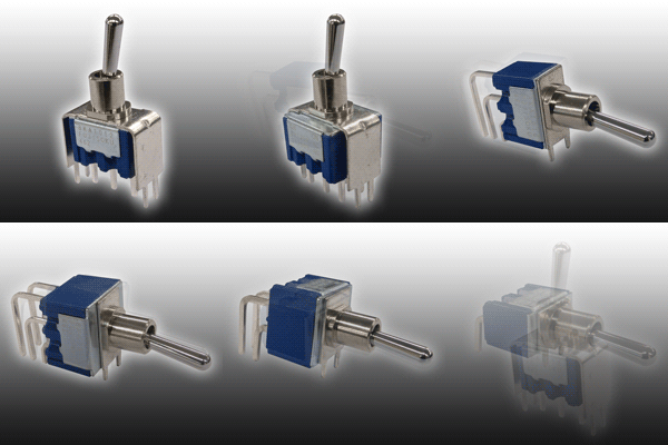
The 8KA Toggle Switch is designed for PC boards and are
easily mountable on the board. A PC support terminal is
provided for stable mounting. -
Suitable for applications where panel space is limited and a larger toggle is needed.
-
Terminal style : Straight, Right angle and vertical mount PC terminals.
-
Epoxy resin case : UL94V-0 self-extinguishing epoxy.
-
Insulation between terminal and ground : 4 mm minimum. Prevention of flux entry The epoxy resin seal on bottom of the switch helps prevent the entry of solder and flux.
-
Insulation barrier : Insulation barrier design between poles helps prevent short-circuiting between poles ensuring high reliability.
Part number designation
| 8 | K | 1 | 01 | 1 | C- | Z |
|---|---|---|---|---|---|---|
|
Series code |
Actuator shape K: Board mounting
|
Number of poles 1:1 pole |
Switching function 01:ON-ON |
Terminals 2:PC Straight |
Contact material/Plating None:Bs+Ag or Cu+Ag/Ag C:Bs+Ag or Cu+Ag/Ni+Au
Bs=Brass |
◆Terminals

List of part numbers
| Part number | Circuit | Terminals | Switching function | CAD |
|---|---|---|---|---|
| 8KA1012-Z | SPDP | PC Straight | ON-ON | |
| 8KA2012-Z | DPDT | PC Straight | ON-ON | |
| 8KA1014-Z | SPDP | Right Angle | ON-ON | |
| 8KA2014-Z | DPDT | Right Angle | ON-ON | |
| 8KA1016-Z | SPDT | Vertical Mount | ON-ON | |
| 8KA2016-Z | DPDT | Vertical Mount | ON-ON |
Standard Specifications
| Rating Max. | AC125V 6A AC250V 3A DC30V 4A |
|---|---|
| Initial contact resistance | 10mΩ Max. (DC2~4V 1A) |
| Initial dielectric strength | AC1500V 1minute |
| Initial insulation resistance | 1000MΩMin. ( DC500V) |
| Electrical life | 50,000cycles |
| Operating temperature range | -30~+85℃ |
| Storage temperature range | -40~+85℃ |
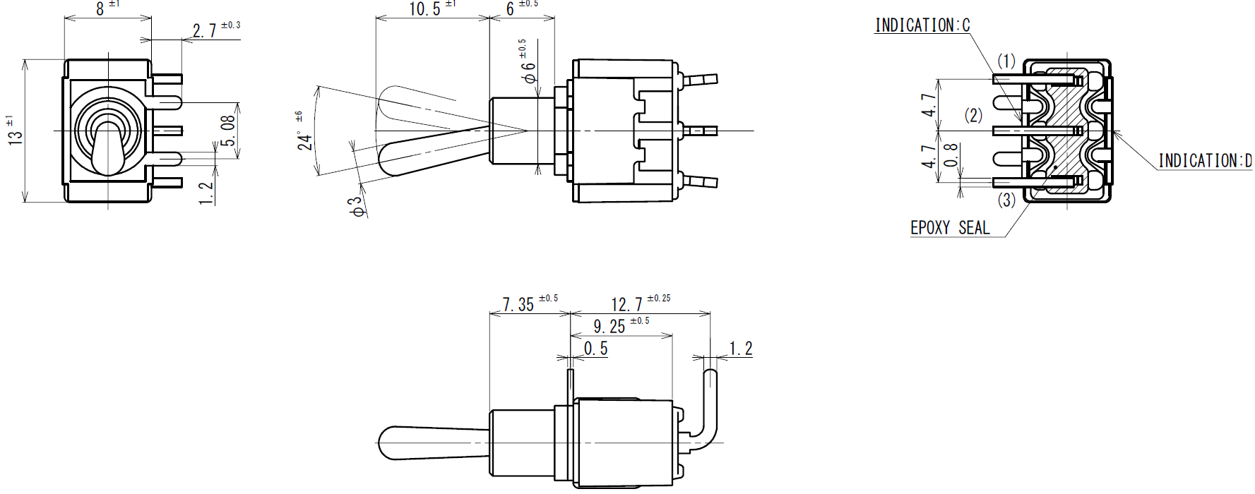
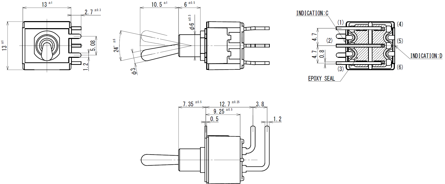
Outline dimensions
(Unit: mm)
●8KA1012

● 8KA2012

● 8KA1014

● 8KA2014

● 8KA1016

● 8KA2016

PC Hole Layouts

Precautions
Soldering Specifications
- Manual soldering/ Device:Solder iron
①350°C Max. 3 sec. Max. ②310°C Max. 7 sec. Max. - Auto soldering:275°C Max. 6 sec. Max.
The above-stated soldering conditions shall apply only to switches with straight terminals.
Auto soldering is not possible with rightangle terminals. Switches with right-angle terminals should be soldered manually according to the conditions specified in manual soldering above. - When soldering two or more terminals to the common land, use the solder resist to isolate the terminals.
Flux Cleaning
- Solvent : Fluorine or Alcohol type.
- 8K・8KA series are not washable. To wash the PC board, clean the soldering surface of the PC board with a brush so that the switch is not exposed to the cleaning solution.
- Cleaning after soldering should be done after the terminal temperature falls to 90°C or below, or after leaving the switch for five minutes or longer at room temperature.
Mounting
- Do not bend the terminals before mounting the switch on the PC board.
- After mounting the switch, do not place the device in such a way that the device weight will be applied on to the actuator of the switch.
Mounting Accessories
- Mount the accessories after soldering.
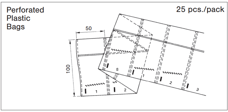
Packaging specification
(Unit:mm)

Documents
Environmental Certificate
- ●The above contents and descriptions are subject to change without notice.


