Pushbutton switch CFP2
Ultra-miniature pushbutton switch
- Ultra-miniature pushbutton switch for high density mounting.
- Washable.
- Terminal pin pitch: 2.54 mm.
- Independent detent mechanism ensures light operational feel.
- Clip contact mechanism for long-term contact reliability.
- Gold-plated contacts.
- Terminal Pins: Straight
- Actuator Color: Gray
Specifications
| Rating | 0.4VA( 28VDC max.) 1μA 20mVDC |
|---|---|
| Initial contact resistance | 100m Ω以下(AC200μV 1.5mA) |
| Dielectric strength | 250VAC 1 minute |
| Insulation resistance | 500MΩ min. ( 250VDC) |
| Electrical life | 10,000 operations at max.rating 30,000 operations at min.rating |
| Mechanical life | 30,000 cycles |
| Operating force | 47±0.98 N |
| Operating temperature range | -40~+85℃ |
| Storage temperature range | -40~+85℃ |
Part number designation
| CFP2 - | 2 | R | C4- | A | W |
|---|---|---|---|---|---|
|
Series Actuator P:Pushbutton |
Number of poles 01: 1 bit |
Switching function 1 pole:F /ON -(ON) 2 poles:R /ON -(ON) |
Terminal style C: P/C C4: Right angle C6: Vertical mounting |
Actuator shape A: Standard |
Packaging W: tray |
List of part numbers
| Part number | Number of poles | Switching function | Terminal style | Packaging | CAD |
|---|---|---|---|---|---|
| CFP2-1FC-AW | 1 bit | ON -(ON) | P/C | tray | |
| CFP2-2RC-AW | 2 bits | ON -(ON) | P/C | tray | |
| CFP2-1FC4-AW | 1 bit | ON -(ON) | Right angle | tray | |
| CFP2-2RC4-AW | 2 bits | ON -(ON) | Right angle | tray | |
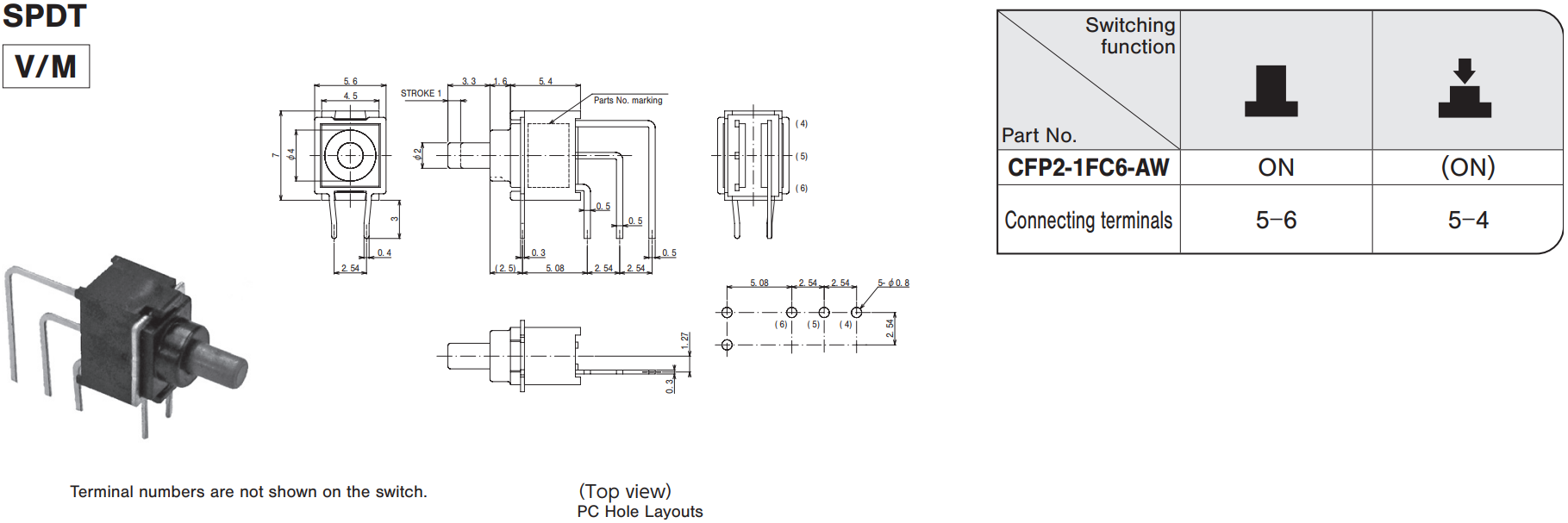
| CFP2-1FC6-AW | 1 bit | ON -(ON) | Vertical mounting | tray | |
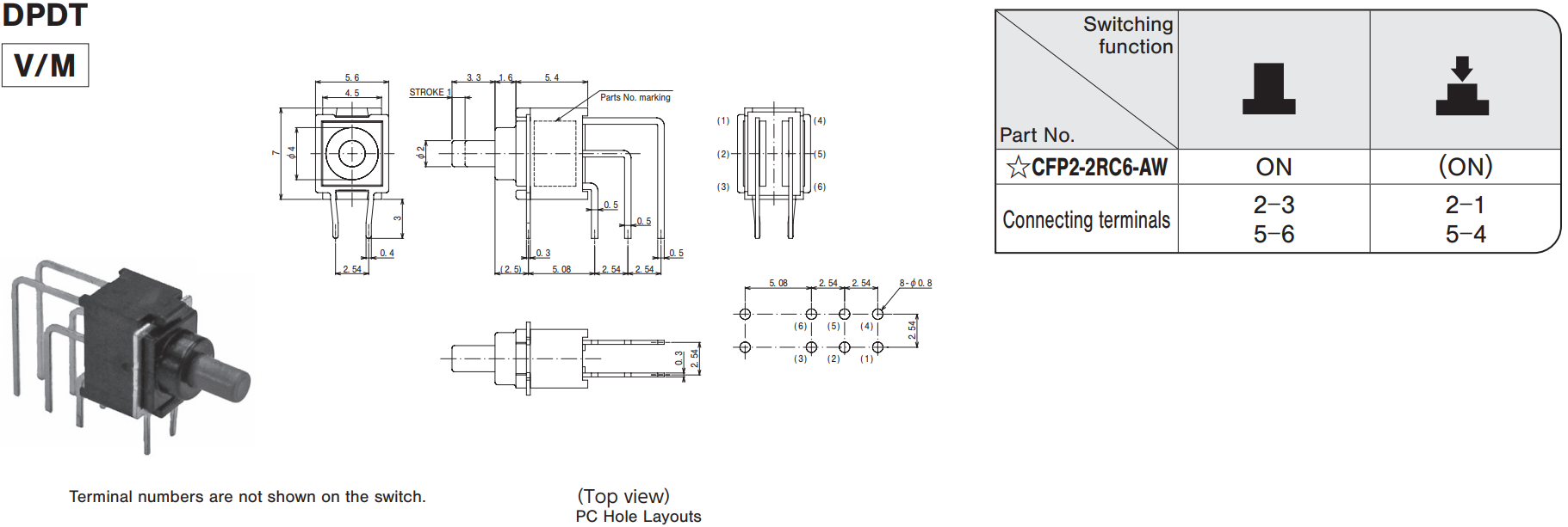
| CFP2-2RC6-AW | 2 bits | ON -(ON) | Vertical mounting | tray |
Outline Dimensions
(Unit:mm)


Handling Specifications
| Soldering Specifications |
|
|---|---|
| Flux Cleaning |
|
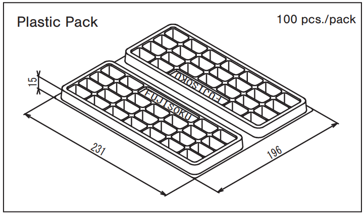
Packaging Specification
(Unit:mm)

Documents
Environmental Certificate
- ●The above contents and descriptions are subject to change without notice.


