Slide switch CUS
Low-profile Slide Switches
FeaturesFeatures
- Low-profile of 1.4 mm
Part Number Designation
| CUS - | 1 | 2 | T | B |
|---|---|---|---|---|
|
Series name |
No. of poles 1:1 pole |
No. of contacts 2:2 contacts |
Form of packaging T:Taping |
Shape of terminal B:Gull wing |
List of Part Numbers
| Part number | No. of poles | No. of contacts | Shape of terminal | Pieces in package | CAD |
|---|---|---|---|---|---|
| CUS-12TB | 1 | 2 | Gull wing | 2500 pcs./reel | |
| CUS-13TB | 1 | 3 | Gull wing | 2500 pcs./reel | |
| CUS-14TB | 1 | 4 | Gull wing | 2500 pcs./reel | |
| CUS-22TB | 2 | 2 | Gull wing | 1400 pcs./reel |
Standard Specifications
| Operating temp. range | − 20 ~ 70 °C |
|---|---|
| Storage temp. range | − 40 ~ 85 °C |
| Sealing | Non washable |
| Net weight | Approx. 0.08 g (CUS-12) Approx. 0.10 g (CUS-13) Approx. 0.13 g (CUS-14) Approx. 0.11 g (CUS-22) |
Electrical Characteristics
| Contact rating | Non-switching:DC50 V 100 mA Switching:DC4 V 300 mA Minimum:DC20 mV 1 μA |
|---|---|
| Contact timing | Non-shorting |
| Contact resistance | 70 mΩ maximum |
| Insulation resistance | 100 MΩ minimum (DC 100 V) |
| Dielectric strength | AC100 V 60 s |
Mechanical Characteristics
| No. of positions | 2, 3, 4 |
|---|---|
| Stroke | 1.5 mm |
| Stop strength | 10 N {1.02 kgf} 15 s |
| Solderability | 245 ± 3 °C 2 ~ 3 s |
| Soldering heat | Reflow peak : 250 ~ 255 °C Manual soldering : 350 ± 10 °C 3 ~ 4 s |
| Shear | 5 N {0.5 kgf} 10 s |
| Substrate bending | Width 90 mm, bend 3 mm, 5 s, 1 time |
| Pull-off strength | 5 N {0.5 kgf} 10 s |
| Operating force |
|

Environmental Characteristics
| Vibration | Amplitude 1.5 mm or Acceleration 98 m/s2,10-500-10 Hz, 3 directions for 10 cycles each |
|---|---|
| Shock | 490 m/s2, 11 ms, 6 directions for 3 times each |
| Load life | Continuous load 10000 cycles, DC4 ± 0.5 V, 300 ± 10 mA |
| Humidity | 40 °C, Relative humidity 90 ~ 95 %,240 h, No load |
| High temp. exposure | 85 °C, 96 h, No load |
| Low temp. exposure | − 40 °C, 96 h, No load |
| Thermal shock | − 40 (0.5 h) ~ 85 °C (0.5 h), 5 cycles |
Outline Dimensions
Unless otherwise specified, tolerance : ± 0.2 (Unit : mm)


Recommended P.C.B. Pad Outline Dimensions
(Unit : mm)


Packaging specifications
Taping version is packaged in 2500 pcs. par reel (1400 pcs. for CUS-22).
Taping version is boxed with 1 reel (2500 pcs. or 1400 pcs.).
Maximum number of consecutive missing pieces = 2.
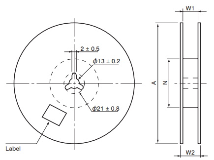
Leader length and reel dimension are shown in the diagrams below.
-
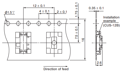
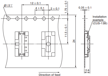
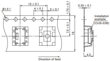
Embossed tape dimensions

(Unit:mm)
-
● CUS-12TB

-
● CUS-13TB, 14TB

-
● CUS-22TB
(Unit:mm)
● Reel dimensions

Reel shape and dimensions
| Part Number | A | W1 | W2 | N |
|---|---|---|---|---|
| 12TB, 22TB | φ 330 ± 2 | 17.4 ± 1 | 21.4 ± 1 | φ 80 ± 1 |
| 13TB, 14TB | φ 330 ± 2 | 25.4 ± 1 | 29.4 ± 1 | φ 80 ± 1 |
Documents
Environmental Certificate
- ●The above contents and descriptions are subject to change without notice.


